
A Swing-Beam Barn

A couple of years ago, we moved our shop from the vicinity of Kingston, Ontario, to a new location about 50 miles away. This involved converting a barn into a workshop, moving tools and people, and transporting our inventory of barn frames. During the move, my wife and I firmly agreed not to take any more barns into inventory, as our core business is new frames. We were almost finished with this large move for our small company when I received a call from a client in our original neighborhood. He wanted a barn removed from his property as it was no longer in use and its roof would need repair soon. I weakened and went back to take a look. Standing up to my waist in old hay, ancient farm machinery and a variety of wildlife, I called my wife and said, “You have to see this one.” This barn had a five-bent, 30x48-ft. canted purlin post white pine frame in good condition. Those in a similar business and carrying the same defective gene know there was no option but to dismantle the building and bring it home.


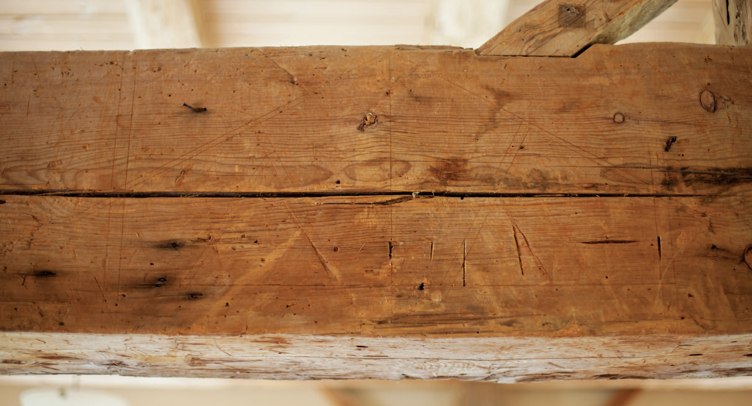
We decided to re-erect this building right away as a show house for our company’s work. (Visiting firemen are welcome too.) We brought the timbers home, washed them, made drawings for a structural review, re-erected the frame and fitted it out as a house. Throughout the dismantling, shipping and cleaning, we never noticed an original drawing on the swing-beam bent. When the reassembled frame was standing on the new subfloor, one of our framers pointed it out. For me this was a great find. I have always wondered how the layout was done for the canted purlin post and what sort of plans were used in the mid-1800s. The drawing is scratched into the swing beam with an awl or knife, a scale drawing at one inch to the foot, and done accurately. The timbers appear to be drawn not as actual but as sized: although the canted purlin posts are hewn to 7 in., they are represented by ½ in. on the plan and in fact sized to 6 in.
As far as I can tell, the drawing sequence went thus: 1. The 30-ft. dimension was set, then the roof pitch drawn at 7 in 12 and a 4-in. depth drawn for the rafter. 2. The upper face of the canted purlin post was laid out on the top of the tie beam at 2 ft. 6 in. from centerline and angled to hit the midspan of the rafter. 3. The upper face of the strut was laid out 2 ft. down the canted purlin post from the top and 4 ft. in from the outside wall on the tie. I do not see any arcs struck to create this layout, and the dimensions cited are calculated directly from the scale drawing. My guess is that the rafter length was taken from the scaled drawing, as well as the lengths and angles of the roof members. This drawing is a nice window into the working world of the past.